Flight Testing
Startup and Shutdown Procedures
Startup Procedure
- Connect the battery to the drone.
- Connect the PC to the same network as the FC.
- Launch
TobasGCS. - Click
Load Projectand loadtobas_f450.TBS. - Click
Control Systemin the tool buttons to open it. - Pass the pre-arm safety checks and confirm that
Ready to Armis lit green. - Turn on the transmitter, turn on the
Enableswitch, and turn off theKillswitch. - Select the flight mode using the transmitter switch. Initially,
Stabilize(attitude control mode) is safe. - Arm by holding the throttle stick down and the yaw stick to the right for 1 second.
- After arming, return the yaw stick to center and gradually raise the throttle stick.
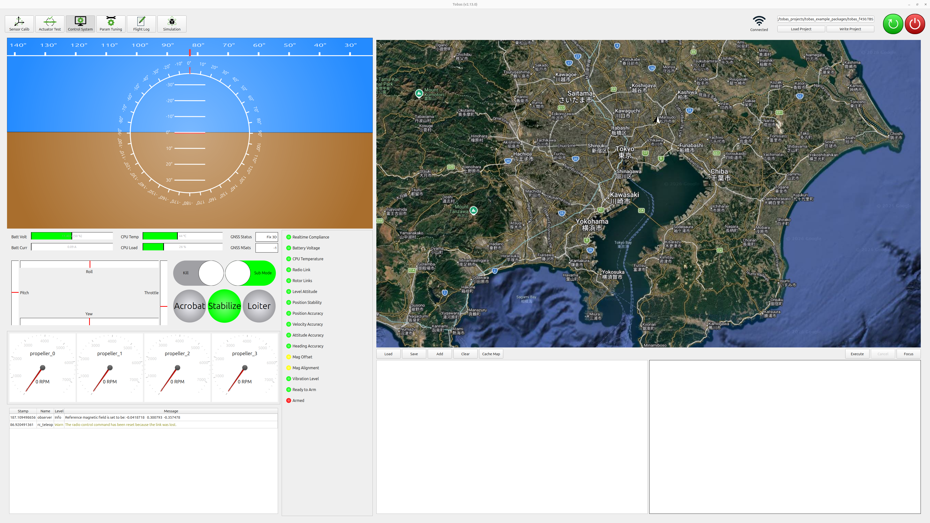
Note
In environments where GNSS cannot be used, such as indoors, the position- and velocity-related checks cannot be passed, so you need to disable those checks in the Fail-Safe tab of Setup Assistant.
Shutdown Procedure
- After landing, the drone will automatically disarm after a certain period while the throttle stick is kept low.
Alternatively, you can disarm immediately by turning on the
Killswitch. - Click the GCS power button (red) to shut down the FC.
- Taking sufficient care for safety, cut power to the FC and ESC.
The following sections describe each function of the ground control station.
Control System
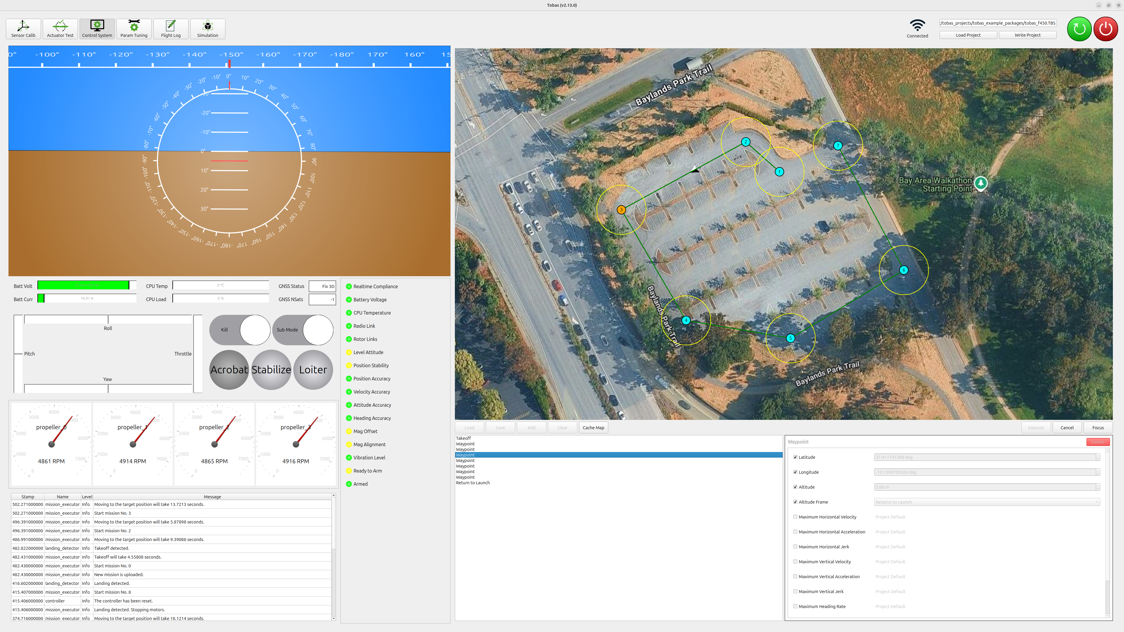
Control System is a tool for monitoring the drone status and planning missions.
Status Monitoring
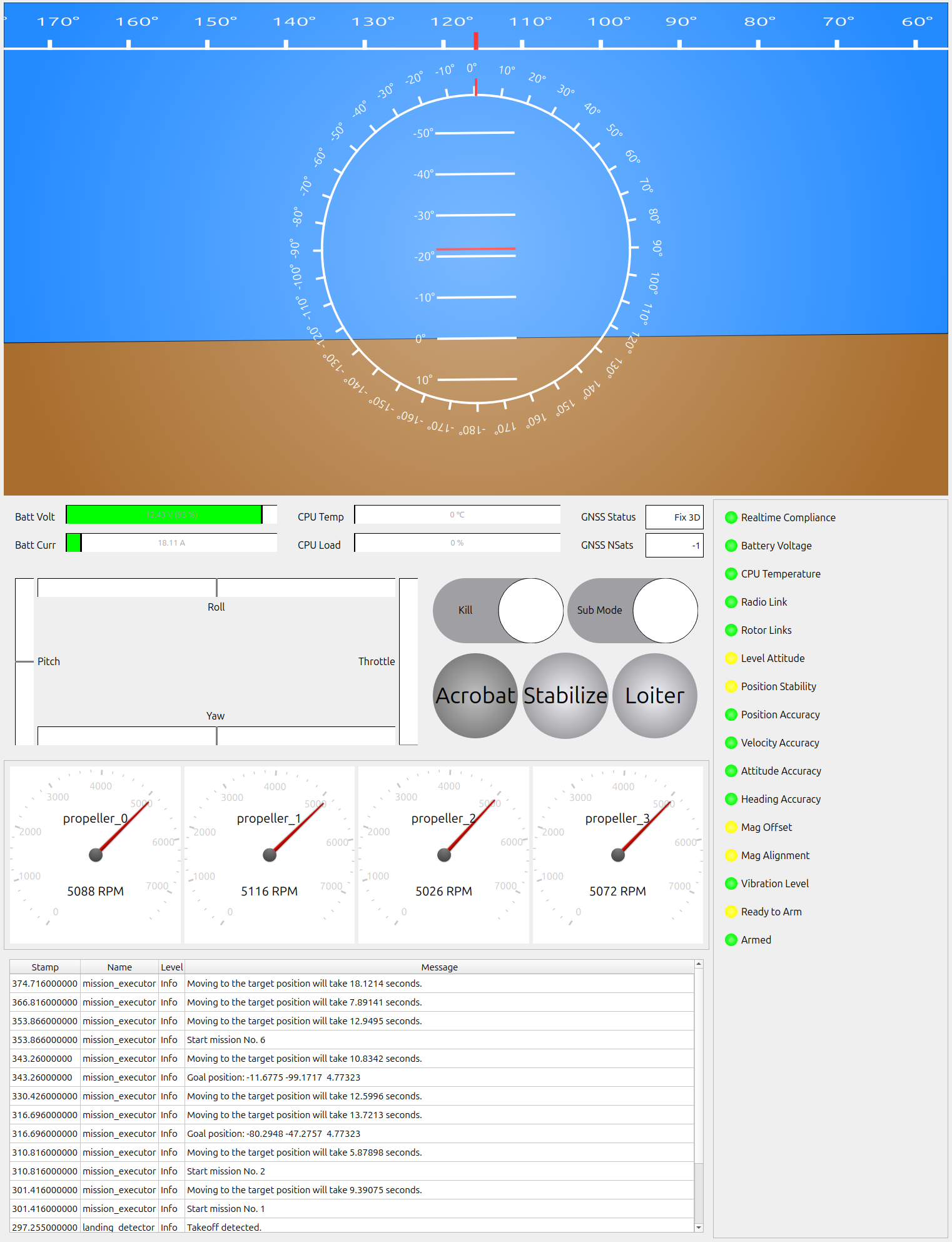
The left side of the screen is the status monitoring area, where the following information is displayed:
- Attitude: roll, pitch, yaw
- Battery status: voltage, current
- CPU status: temperature, load
- GNSS status: status, number of satellites
- RC input: sticks, kill, flight mode, other switches
- Status of each motor: rotation speed, communication status
- Status: Pre-Arm Check, Post-Arm Check, etc.
- Messages from each node
Mission Planning
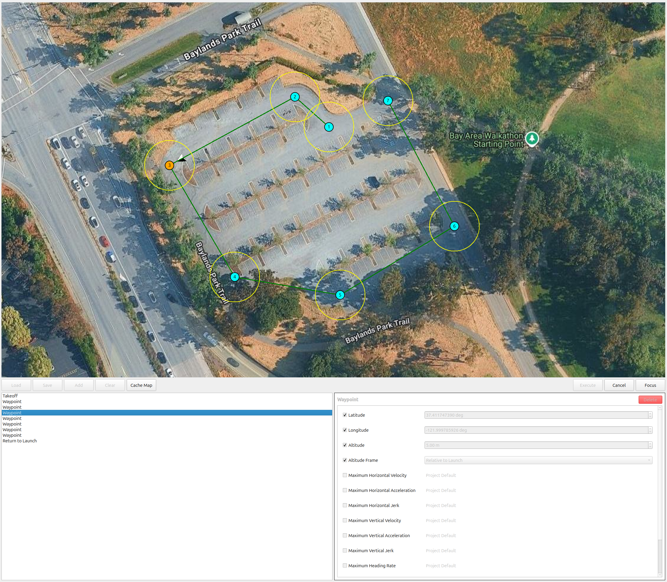
The right side of the screen is the mission planning area, where you can plan and execute flight missions.
- Click
Addto add commands. In the figure below, a mission is planned that performsTakeoff, passes through 9Waypoint, thenReturn to HomeandLand. - Set the parameters for each command using the dialog at the bottom right of the screen. Waypoint coordinates can also be adjusted by dragging and dropping the icons on the map.
- Press the
Executebutton to execute the mission.
Note
If the Enable switch on the transmitter is on, transmitter commands take priority,
so be sure to execute with it turned off.
Param Tuning
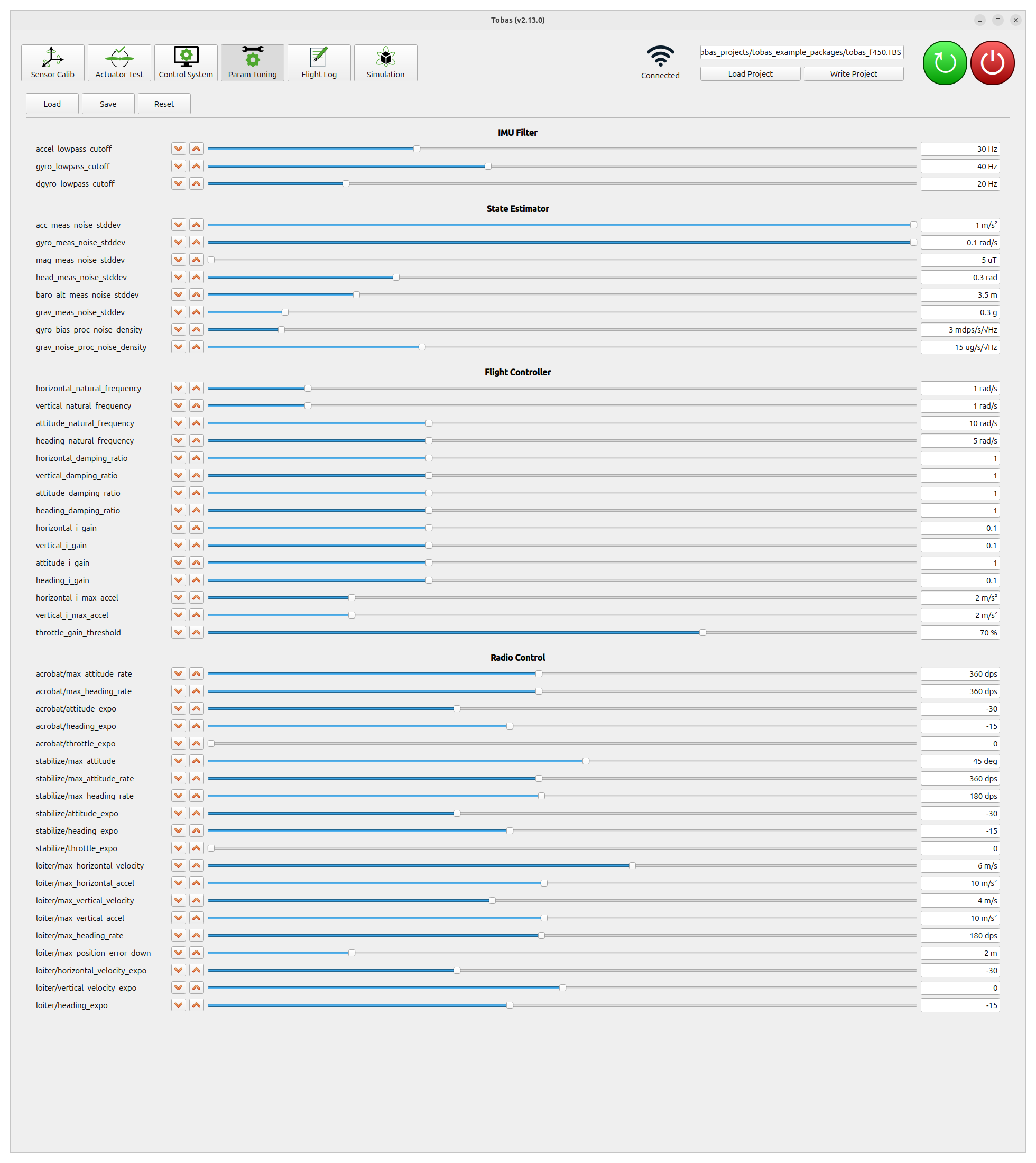
Param Tuning is a tool for tuning flight-related parameters online.
Procedure
- Click
Loadto load the current parameters from the FC. - You can tune parameters online using the increment/decrement buttons or sliders.
- Click
Saveto save the current parameters in the project folder on the local PC. - After the flight, click
Writeto flash the saved parameters to the FC.
Main Parameters
attitude_natural_frequency
This parameter relates to the responsiveness of attitude control. A larger value makes the response to the target attitude faster, but if it is too large, attitude control becomes unstable. Increase the value gradually while confirming that no oscillation occurs. For this airframe, it could be increased up to 25rad/s.
heading_natural_frequency
This parameter relates to the responsiveness of heading control. A larger value makes the response to the target heading faster, but if it is too large, heading control becomes unstable. Increase the value gradually while confirming that no oscillation occurs. This time, we left it at the default value.
horizontal_natural_frequency
This parameter relates to the responsiveness of horizontal position control. A larger value makes the response to the target position faster, but if it is too large, position control becomes unstable. Increase the value gradually while confirming that no oscillation occurs. This time, we left it at the default value.
vertical_natural_frequency
This parameter relates to the responsiveness of vertical position control. A larger value makes the response to the target altitude faster, but if it is too large, altitude control becomes unstable. Increase the value gradually while confirming that no oscillation occurs. This time, we left it at the default value.
lowpass_filter/gyro_cutoff
This is the cutoff frequency of the gyroscope sensor’s low-pass filter. A lower value suppresses gyroscope noise more strongly, but if it is too low, the signal delay may destabilize angular rate control. Check the flight log, described later. If the motor RPM target oscillates with an amplitude of 10% or more of the hovering RPM, consider the post-filter angular rate oscillation to be too large and reduce this value. This time, we left it at the default value.
Tip
Depending on the FMU, an RPM filter that efficiently attenuates propeller vibrations may be available, and it can be configured here in the same way as the parameters above. Since this is a powerful feature, we recommend enabling it.
Flight Log
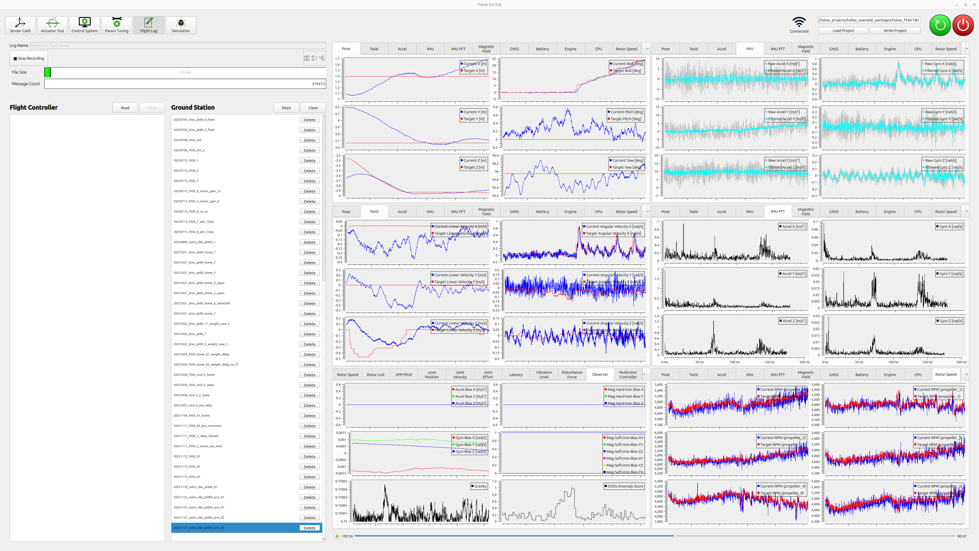
Flight Log is a tool for recording and replaying in-flight status.
Recording Flight Logs
- Enter a log name in
Log Name(example: 20260101_f450_hover). - Press the
Start Recordingbutton to start recording the log. - Press the
Stop Recordingbutton to stop recording.
Viewing Flight Logs
- Press the
Readbutton on the FC side and the PC side to display the list of logs saved on each side. - Press the
Downloadbutton to the right of a log name in the FC-side list to download the corresponding log to the PC side. - Click a log name in the PC-side list to plot the saved data on the right side.
- You can control the displayed log time using the play/stop buttons and slider at the bottom right.